 A DC bus never crosses zero. When a contactor opens under a DC load, the arc that forms between the parting tips does not go out on its own; the contactor has to stretch it, cool it and quench it. There are two ways to build a contactor that can do that, and both are on the market: contacts sealed in a chamber of inert gas, or contacts in open air with a magnetic field that blows the arc into a chute. Which one belongs in your design depends less on the headline numbers than on what the part has to do over the life of the machine.
Why DC is the hard case
AC current passes through zero twice a cycle, more than a hundred times a second at 60 Hz. When AC contacts open, the arc dies at the next zero crossing and the gap only has to recover its dielectric strength fast enough that the arc does not restrike. The waveform does most of the work, which is why an AC contactor can be small for its rating.
DC has no zero crossing. The current holds its value and its direction, so the arc that forms when the contacts part keeps burning until the gap gets long enough, and the arc column cold enough, that the supply voltage can no longer sustain it. The higher the voltage, the longer that gap has to be. Left to itself the gap would have to be so wide that the coil moving the contacts would be enormous. Every DC contactor design is a way of getting the same result in less space.
The same knife switch breaking an AC load and then a DC load. The AC arc dies at the zero crossing; the DC arc has to be pulled apart.
Two ways to put the arc out
Sealed gas-filled contactors
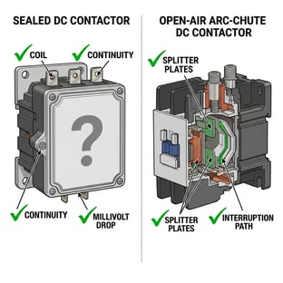
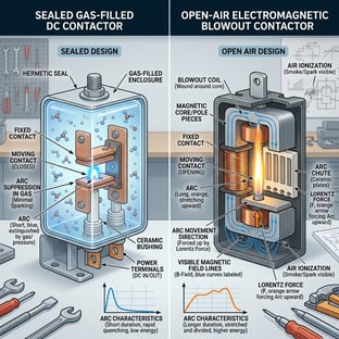
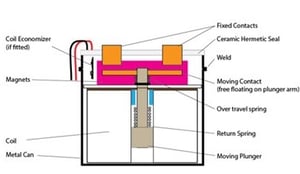 The contacts sit inside a sealed chamber filled with an inert gas, usually a hydrogen mix. Hydrogen conducts heat well and has a high dielectric strength, so the gas cools the arc and helps the gap recover. A permanent magnet inside the can pushes the arc off the tips. The result is a compact package for its voltage rating, sealed against dust and moisture, with no arc products vented into the enclosure. Those are real advantages, and in a tight space or a washdown environment they can be the deciding ones.
The trade is that the chamber is the part. It cannot be opened, so the contact tips cannot be inspected and cannot be replaced. Whatever the tips look like after a few years of make and break under load is what you have, and the only way to find out is to measure contact resistance from outside. When the part reaches the end of its electrical life the whole contactor is replaced.
Open-air magnetic blowout contactors
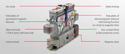
The contacts sit in air, inside an arc chamber that is vented to the enclosure. When the tips part, a magnetic field from permanent magnets or a blowout coil drives the arc sideways off the tips and into an arc chute, a stack of splitter plates that stretches the arc, breaks it into a series of short arcs and cools it until it goes out. The arc spends most of its life in the chute, not on the contact surfaces, so the tips run cooler and can be made of a harder, larger contact material.
Most designs in this family are double-break: two gaps in series on one contact bridge, each of which only has to hold off half the voltage. With the blowout field arranged for it, the same device breaks current in either direction, which matters on a battery bus that charges and discharges through the same contactor. And because the chamber opens, the contact tips and the arc chute can be looked at, measured and replaced.
What the cycle count on the datasheet is counting
The number most often compared between two contactors is the cycle count, and it is usually the wrong number for a DC disconnect. A headline figure of hundreds of thousands or millions of operations is almost always mechanical life, or electrical life at a light load where there is little arc. The break-under-load line, the number of times the part can open its rated DC current at its rated voltage, is far lower, often by a factor in the hundreds. Both families publish it if you ask.
Now look at what the part actually does on a battery system, a DC fast charger or an energy storage rack. The power electronics do the routine switching, millions of times, with no contact wear. A precharge circuit brings the DC link up before the main contactor closes, so the main contactor closes into almost no inrush. It closes a few times a day, sits closed, and has to open once, under a fault, after years in service. Cycle count describes an AC motor starter's duty. For a DC isolator the questions are whether it will break rated current when a fault demands it, whether the tips will have welded by then, and what the contact resistance will be after all those years closed. Our companion post goes through why the specification metric does not apply to this architecture.
Short-circuit: making and holding on
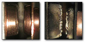 When fault current flows through closed contacts, the current constriction at the contact spot creates an electrodynamic force that tries to lift the tips apart. If that force beats the contact pressure, the tips lift, arc, and weld. The contact force a design can apply is set by the coil, the spring and the space available, and an open-air contactor with a large mechanical drive and large tips can hold on harder. A Schaltbau C303, for example, carries 5,000 A for 20 ms without welding, on a part rated 1,500 V and 500 A continuous in both directions.
The sealed part you are comparing against will have its own short-time withstand and make ratings on the datasheet. Read them at your fault level, not the headline continuous current, and ask what happens after the event: on a sealed part a welded or eroded set of tips is the end of the device, on an open-chamber part it is a service item.
Heat and contact resistance over the life of the part
A contactor's voltage and current ratings are one point on a curve, stated at the device's maximum thermal current. The real limit is heat at the contact spot. Higher current means more resistive heating at the tips, which raises their temperature, which raises their resistance, which raises the heating at the same current. Run below the rated thermal current and there is voltage headroom; run at it and the margin is gone.
Contact resistance is not a constant. Every break under load draws an arc, and the arc erodes and pits the contact surface, so resistance creeps up across the switching life whether the part is sealed or open. In a sealed can that heat has to get out through the terminals and the housing, and the creep is permanent. In an open-air contactor the chamber vents, the tips run cooler because the arc is pulled into the chute, and when resistance has crept far enough the tip set is replaced and the part is back to new. Schaltbau's CT and CP families are built around exactly that: main contact tips and arc chutes designed for inspection and replacement, with the CP frames swapping the arc chamber without tools.
Where each one fits
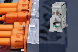 Sealed gas-filled earns its place where the package has to be small, where the environment is wet, dirty or hazardous and the contacts must never see it, and where the part will be replaced as a unit on a schedule anyway. Automotive main contactors at modest current and short design lives are the classic case.
Open-air magnetic blowout earns its place as voltage and current rise, on any bus that carries current both ways, and on any machine whose service life is longer than one set of contact tips. Electric trucks and buses, DC fast chargers, energy storage and solar inverter DC links, battery test benches and burn-in racks, forklifts and AGVs, marine DC systems and rolling stock all run there. Schaltbau has been switching DC on rail since 1929, and the traction duty is where the open-chamber design comes from.
 Neither family is wrong. The mistake is choosing on the cycle count, or on the footprint alone, and finding out on the worst day which job the part was actually built for.
Six questions to ask before the BOM locks
- Which life number is this? Ask for the mechanical line and the electrical break line at your DC voltage and current, and compare only the second.
- Does it break in both directions at full rating? On a charge and discharge bus, ask for the reverse break rating in writing, not the forward one.
- What are the short-time withstand and make ratings at your fault level? And what condition is the part in afterward.
- What is the contact resistance new, and what is the end-of-life limit? Then: can the tips be inspected, and can the set be replaced to reset it.
- What happens to the arc products? A sealed can keeps them in; an open chamber vents them, and the enclosure design has to allow for that.
- Is it a Recognized Component to UL 60947-4-1? The Schaltbau C310 and C320 carry UL Recognized Component marks under file E116641, and their auxiliary contacts have mirror-contact function to IEC 60947-4-1 Annex F for the safety circuit.
Where Schaltbau sits
Every Schaltbau DC contactor is an open-air, permanent-magnet blowout design. The C303 breaks 1,500 V and 500 A continuous in both directions in an open chamber with no gas fill. The CT series covers 1,500 V or 3,000 V at 400 and 800 A with serviceable tips, and the CP frames run to 2,000 A. The product page is at Schaltbau DC contactors, and the one-page Schaltbau at a glance card has the four product families with a photo of each. If you have a disconnect in a design now and the datasheet only shows one life line, send us the part number and we will put the two numbers side by side.
GO DEEPER

Dynamic represents power, control and measurement lines for machine builders and panel shops in Northern California and Northern Nevada. We help at the schematic and bill-of-materials stage, where a DC disconnect is cheapest to change.
Working through a live design question?




.png)