Dynamic Measurement and Control Solutions
    • Applications
      • Industrial Automation & Production Equipment
      • Semiconductor & Test Equipment
      • Robotics, Robot Cells & Mobile Robots
      • Food, Beverage & Process Equipment
      • Life Sciences, Medical & Laboratory Equipment
      • Commercial, Self-Service & Public-Use Equipment
      • Transportation, Mobility & Vehicle Systems
      • Heavy Equipment, Mobile Machinery & Outdoor Systems
      • Energy, Power & Electrification Systems
      • Data Centers & Digital Infrastructure
      • Building, Facility & Site Systems
    • Products
    • Design Path
      • The Design Path
      • Design Once, Build Many
      • Power That Performs
      • Machine Intelligence & Control
      • Industrial Data Pathways
      • Wired to Last
    • Design Guidance
    • The Detail
    Dynamic Measurement and Control Solutions
    Opens mobile navigation.

    Click to call. 4087809190

    • Applications
      • Industrial Automation & Production Equipment
      • Semiconductor & Test Equipment
      • Robotics, Robot Cells & Mobile Robots
      • Food, Beverage & Process Equipment
      • Life Sciences, Medical & Laboratory Equipment
      • Commercial, Self-Service & Public-Use Equipment
      • Transportation, Mobility & Vehicle Systems
      • Heavy Equipment, Mobile Machinery & Outdoor Systems
      • Energy, Power & Electrification Systems
      • Data Centers & Digital Infrastructure
      • Building, Facility & Site Systems
    • Products
    • Design Path
      • The Design Path
      • Design Once, Build Many
      • Power That Performs
      • Machine Intelligence & Control
      • Industrial Data Pathways
      • Wired to Last
    • Design Guidance
    • The Detail

    Let's get in touch

    Fill out this form, and we'll contact you soon.

    Panel Wiring Field Guide · DC switching

    How to read a DC contactor datasheet

    A DC contactor is not an AC contactor with a different label. The arc behaves differently, the ratings mean different things, and the number on the front of the catalog is usually not the number that matters. This guide shows how to read a DC contactor datasheet, and how to pick the part for the event it has to survive.

    Inside

    1. 1Why DC is harder to break
    2. 2Reading the datasheet
    3. 3Utilization categories
    4. 4Which event is this contactor for
    5. 5Polarity and bidirectional switching
    6. 6Coils and economizers
    7. 7Installation
    8. 8Mirror contacts and the safety circuit
    9. 9UL status, stated exactly

    Who it is for

    Engineers who design battery, charger, storage, test bench and DC distribution systems, and the panel shops that build their cabinets.

    It is the long form of section 9 of the Panel Wiring Field Guide.

    1Why DC is harder to break

    When contacts carrying current open, the air between them ionizes and an arc forms. The arc is a conductor at a temperature the factory puts at up to 20,000 C, hot enough to erode the contacts and anything near them.

    On AC, the current passes through zero twice a cycle. The arc dies at the next zero, within about 8 ms at 60 Hz, and the contactor's job is to keep it from restriking. On DC there is no zero. Once the arc forms it burns for as long as the voltage across the gap can sustain it, which at battery voltage can be indefinitely. The contactor has to put the arc out itself.

    Three things put out a DC arc: stretching it until the gap voltage exceeds what the source can drive, splitting it across plates so each short arc needs its own anode and cathode drop, and cooling it. The C303, C310 and C320 do it with permanent magnets. A current-carrying arc sits in the magnet field and the Lorentz force pushes it off the contact tips and up into the arc chamber, where it is stretched and split between insulating plates until it goes out. The chamber is open to air, so the pressure of the arc vents instead of building, and there is no fill gas to lose over the life of the part.

    One consequence worth knowing: a single magnet field pushes the arc in one direction, so a contactor built that way breaks well with current flowing one way and poorly the other way. Schaltbau's arc chamber has two sections with the magnets placed so the arc goes up into the left or right section depending on current direction. That is what "bidirectional" means on the datasheet: the same breaking capability for charge and discharge through one device.

    The other common architecture seals the contacts in a chamber filled with pressurized gas, such as hydrogen or nitrogen, which cools the arc well in a small package. The trade is that the gas is the quench medium. The factory notes that it can leak away slowly over thermal cycling, and that the loss cannot be detected in normal operation. Both architectures have their place; the honest comparison is on identical conditions, both current directions, electrical life at the same breaking current and end-of-life behavior. Our comparison chart lists the eight points and what to ask each vendor. One point goes to the sealed design. An air-break part derates with altitude: the C310 datasheet limits it to 4,500 m at 1,000 V and 3,500 m at 1,500 V, and the C320 to 5,000 m, with more heating above 2,000 m. The break inside a sealed chamber does not depend on altitude.

    2Reading the datasheet
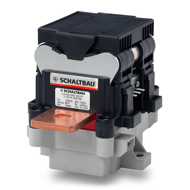
    Schaltbau C310. Ith, Ie and breaking capacity are three different numbers.
    Schaltbau C310. Ith, Ie and breaking capacity are three different numbers.Photo: Schaltbau

    The front of a DC contactor datasheet carries a voltage and a current. Neither is a rating you can design to by itself. Here is what each line on a Schaltbau sheet means, using the C310, C320 and C303 as the examples.

    Rated insulation voltage Ui and rated operational voltage Ue. Ui is the voltage the insulation system is built for; Ue is the voltage at which the switching ratings are stated. They move with pollution degree: the C310K is rated 1,000 V at pollution degree 3 and 1,500 V at pollution degree 2, which is a statement about the enclosure it sits in, not only about the part. The smaller-chamber C310A is rated 1,000 V. The C320 is 1,500 V at PD3 with a 1,800 V Ui. Rated impulse withstand voltage Uimp (10 kV on both) is the surge the gap holds off.

    Conventional free-air thermal current Ith. The current the part carries continuously without exceeding its temperature limits, in free air, with the stated terminal conductor and ambient. It is a carry rating, not a switching rating. The C310/500 carries 500 A at 85 C ambient with 185 mm2 conductors and a 65 K terminal rise; the C320K/1000 carries 1,200 A at 60 C with 800 mm2 and 1,000 A with 600 mm2. Change the copper, the ambient or the enclosure and the number changes. A Schaltbau engineer, writing in Konstruktionspraxis, notes that in a ventilated cabinet it is not unusual to run above Ith by about a quarter, by agreement with the manufacturer, and that the maximum current and the maximum ambient depend on each other (the white paper carries the derating curve). Ask for that curve at your conditions.

    Rated operational current Ie and utilization category. Ie is the current the part is rated to make and break repeatedly, at a stated voltage, for a stated duty. It is far below Ith. The C310 carries 500 A but its DC-1 Ie is 60 A at 750 V under IEC 60947-4-1, and 50 A at 600 V under the UL "DC general use" line. The C320 carries 1,200 A and its DC-1 Ie is 150 A at 1,500 V (IEC) or 80 A at 1,500 V (UL). The electrical endurance figure is stated at its own point. The C310's 6,000 operations are at 750 V and 60 A, its DC-1 rating, at an L/R of 1 ms. The C320's 6,000 operations are at 1,250 V and 120 A, also at 1 ms. A cycle count without its voltage, current and time constant is not a rating.

    Making capacity Icm. The current the contacts can close into without welding, at L/R of zero: 2,500 A on the C310 (monostable, horizontal), 3,000 A on the C320, 2,000 A on the C303. This is the inrush question. If the DC link capacitor is charged through the main contactor, this is the number that decides whether the contacts survive the first close. A precharge contactor and resistor (the C303 has a dedicated precharge variant) brings the bus up first so the main contactor closes into almost nothing.

    Short-time withstand current Icw. The fault current the closed contacts carry for a stated time without welding, so the fuse has time to clear: 3,000 A for 1 s on the C310, 4,500 A for 100 ms on the C320, 5,000 A for 20 ms on the C303. The white paper's short-time table for the 500 A class runs from 600 A for 600 s to 12,000 A for under 5 ms. Current through the closed contacts also creates a magnetic force that pushes them apart, and that force climbs steeply with fault current. The contact spring force is what holds the part closed through the let-through.

    Breaking capacity. The current the part can interrupt at a stated voltage and a stated circuit inductance, with the number of operations it is good for at that point. The C310K table is given at a maximum of 0.25 mH, each point good for ten to twenty-five operations:

    VoltageOne contactTwo contacts in series
    1,500 V300 A1,000 A
    1,000 V500 A1,500 A
    900 V700 A
    750 V1,000 A
    500 V1,500 A

    The smaller-chamber C310A has its own, lower table. The C320K/1000 is printed at the circuit time constant, thirty operations at each point:

    VoltageTime constant L/RBreaking current
    1,500 V0.15 ms800 A
    1,500 V1 ms450 A
    1,000 V0.2 ms1,600 A
    1,000 V1 ms1,300 A

    Read the inductance column every time. The energy the arc has to absorb rises with the circuit inductance, and the factory's example is that the C294's breaking capacity rises by 300 percent when the circuit time constant drops from 15 ms to 1 ms. A breaking rating proven in a low-inductance test circuit does not transfer to a long cable run to a battery string.

    Pole impedance and power loss. The contact resistance sets the heat. About 120 microohm on the C310, about 50 microohm on the C320 (50 W per pole at 1,000 A), typical 100 microohm on the C303. Loss rises with the square of current, so at 1,000 A the difference between 50 and 150 microohm is 100 W of heat per pole that the enclosure has to shed.

    Mechanical endurance. Operations with no current: 2,000,000 on the monostable C310, 1,000,000 on the C320. This is the headline number on most catalogs and it is the one that matters least for an isolator.

    3Utilization categories

    IEC 60947-4-1 (Edition 4.0, 2018-10, clause 5.4 and Table 1) defines the duties a contactor is tested for. The AC categories are familiar: AC-1 for resistive and slightly inductive loads, AC-3 for squirrel-cage motors broken running, AC-4 for plugging and inching. The DC categories are DC-1 for non-inductive or slightly inductive loads, DC-3 for shunt motors (starting, plugging, inching, dynamic braking), DC-5 for series motors under the same duties, and DC-6 for incandescent lamps. UL 60947-4-1 is the US version harmonized to it, and the UL rating line on a Schaltbau sheet reads "DC-1 / DC general use".

    Two things follow. First, the only DC categories with hard repetitive switching are the motor categories, and a battery isolator, a bus contactor or a charger output contactor is none of those. Its honest category is DC-1, which was never written around cycle count. Second, an AC-3 rating says nothing about DC. An AC contactor's DC rating, where it has one, can sit far below its AC voltage, because the AC rating assumes a current zero that DC never provides. The reverse can hold for a DC part. The C310 carries an AC-1 rating of 60 A at 750 V, up to 60 Hz, the same point as its DC-1 rating, because the AC arc dies on its own.

    4Which event is this contactor for

    Ask what the contactor's job is before asking how many cycles it does. In a battery system, a storage string, a solid-state transformer or a DC charger, the power electronics do the routine switching, millions of times, with no contact wear. The contactor holds galvanic isolation (the one thing a semiconductor cannot provide), carries current with low and stable resistance for years, and breaks a fault the handful of times in its life that one occurs. The factory's own guidance is that in battery storage and automotive the contactor usually switches without load, that load breaks are emergency shutdowns, and that the mechanical life is then the relevant figure; it adds that industrial and rail duties with hundreds of thousands of load breaks are what the CT series is built for, while the C310 class is for applications where load breaks are rare and the circuit inductance is low.

    So the specification for an isolator reads: proven breaking capacity at the actual fault voltage, current and inductance; the break curve, not the mechanical headline; contact resistance initial and end of life, and whether the contacts can be inspected or replaced; short-time withstand coordinated with the fuse; anti-weld integrity after years closed. For a test bench, where every cycle ends in an open under load and an emergency stop is a normal event, the electrical life at the bench's actual voltage and current is the first number, and contacts you can inspect are what keep the bench running. The CT frame's main contact tips and arc chute can be inspected and replaced; the CP frame's tips can be inspected and its arc chamber changed without tools.

    Fuse coordination belongs here. The C310 sheet names the fuse it was tested with for type 2 coordination (a SIBA SQB-DC aR fuse at 900 V DC and 10 kA prospective, 200 A on the 150 frame, 315 A on the 300 frame, two 250 A in parallel on the 500 frame). Type 2 means the contactor is still serviceable after the fault. Use the named fuse class or ask the factory to characterize yours.

    5Polarity and bidirectional switching

    Any circuit where current flows both ways needs a contactor that breaks both ways: a battery that charges and discharges, a vehicle that regenerates, a charger that feeds the grid, a storage string that can take or give power. In a battery disconnect unit the main contactors sit in both the positive and negative paths; in a charger the two poles form two independent switching elements; in a storage system the contactors connect and isolate each battery bank from the DC bus, and must break full load if a fault occurs. Ask which position the contactor sits in, and ask for the breaking capacity in both directions; not every DC contactor is rated to break in both directions, and a single-magnet design can be much weaker in reverse. The C303, C310 and C320 are rated bidirectional by construction.

    6Coils and economizers

    A DC contactor coil needs a large pull-in force and a much smaller holding force. The Schaltbau drives use an integrated PWM module to do the pull-in at full power for a fraction of a second and then hold at a few watts: 50 W for 0.2 s then 2.6 W on the C310, 120 W then 11 W on the C320. The coil's operating range is wide (9.5 to 36 V on the 12 to 24 V C310 coil, 16.8 to 30 V on the 24 V C320 coil) and the controller holds the switching behavior constant across ambient. A bistable version of the C310 draws no power in either end position. It switches on a reversed-polarity voltage pulse of 0.1 to 0.5 s. Its making capacity is 750 A, against 2,500 A for the monostable.

    Two installation points from the manuals. The coil suppression is built in and tuned to the contactor's opening time; adding an external freewheeling diode across the coil slows the opening and changes the breaking behavior, and the C303 manual says not to do it. Second, the operating range is the design margin for the control circuit, so the 24 V DC drop on a long control run (section on conductors; NEC Chapter 9, Table 8 for conductor resistance) comes out of it. Size the control conductor so the coil sees its range at the pull-in current, not only at the holding current.

    7Installation

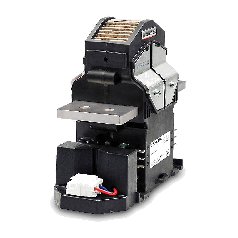
    Schaltbau C320. Mount it in a position the datasheet allows; never upside down.
    Schaltbau C320. Mount it in a position the datasheet allows; never upside down.Photo: Schaltbau

    An open-chamber contactor vents arc plasma through the openings in its arc chamber. The factory manuals ask for three things: the minimum clearances to grounded, magnetic or magnetized parts on all sides and above the chamber (the values are in each catalogue), enough ventilation in the mounting area to carry the plasma away, and a mounting position within the ones the sheet allows (horizontal or vertical, never upside down for the C320; the making capacity of the C310 falls from 2,500 A horizontal to 2,000 A vertical). Switching near the maximum breaking capacity may need larger clearances; ask.

    Terminal torque and conductor size come from the sheet: M8 at 10 to 12 Nm and 600 to 800 mm2 on the C320, M6 at 5 to 6 Nm on the C303, M8 at 4.8 to 6 Nm on the C310/150 and M10 at 8 to 10 Nm on the /300 and /500, with the conductor the sheet ties to each current rating, from 50 mm2 up to 2 x 150 mm2. Control wiring differs by part. The C310 coil lands on 6.3 x 0.8 mm flat tabs and its auxiliaries on 2.8 x 0.5 mm tabs. The C320 auxiliaries take 6.3 x 0.8 mm receptacles. The C320 coil takes a screwless terminal, 0.5 to 1.5 mm2 with a ferrule or up to 2.5 mm2 without. The C303 uses a 5-pin push-in connector rated to 1.5 mm2, or 4.8 x 0.5 mm tabs on some versions. The part needs an enclosure. The C310 and C320 sheets give its own ingress rating as IP00.

    8Mirror contacts and the safety circuit
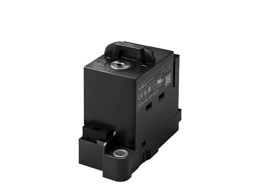
    Schaltbau C303. The mirror contact is built in.
    Schaltbau C303. The mirror contact is built in.Photo: Schaltbau

    A controller that opens a contactor needs to know the contacts actually opened. A welded main contact with a normal auxiliary reporting "open" is the failure a safety circuit exists to catch. IEC 60947-4-1 Annex F defines the mirror contact: an auxiliary NC contact that cannot be closed while the main NO contact is closed. The C303 carries one integrated, the C310 up to two, the C320 up to four auxiliaries of which two can be mirror contacts. The mirror contact is a feedback element for the safety circuit; whether the system meets a performance level is the machine's functional safety assessment, not the contactor's rating.

    9UL status, stated exactly

    The C310 and C320 are UL Recognized Components to UL 60947-4-1 under file E116641. The UL general-purpose rating on file for the C310 A and K versions is 50 A at 600 V DC (DC-1), as printed on the datasheet. The higher breaking figures in section 2 are the factory's datasheet ratings. Both UL files also carry special-use breaking ratings at a circuit inductance under 0.25 mH, and the C320 sheet prints its table with that label. Confirm each figure and its operation count against the UL file before it goes on a drawing. The UL files also carry conditions of acceptability; ask for them before a UL 508A drawing. When a UL 508A panel shop asks whether a rating is "UL", the answer is the file's rating line, and anything above it is confirmed against the file before it goes on a drawing. The C303 is built to IEC and UL 60947-4-1; confirm its file status at quote time. For rail, the C320 and the CT series are built to IEC 60077-2, IEC 61373 for shock and vibration and EN 50124-1 for insulation coordination, and the CP flyer names EN 60077-2 and EN 50124; for vehicles, the C310 and C320 are tested to ISO 16750-3.

    Specifying the contactor

    Four numbers start the selection: system voltage, system current, coil voltage, and whether you need a feedback contact. After that comes the event: the fault voltage and current the contactor must interrupt, the inductance at its terminals, and whether it breaks the fault or only rated load. Where the duty needs a test, the factory's engineers can run it.

    Choosing a DC contactor? Have those numbers in hand, and we help you specify it.

    Schaltbau DC contactors: https://www.dynamicrep.com/schaltbau-dc-contactors

    Sources

    Manufacturer data (datasheets of record)

    • Schaltbau C310 datasheet C2215/2407/0 (July 2024); C320 datasheet C2217/2605/0 (May 2026) and installation manual V2.0 (2023-10-26); C303 datasheet C2283/2604/0 (April 2026) and installation manual V1.0 (2025-05-16); CT catalogue C21.en (June 2015); CP flyer C40.en (April 2019).
    • Schaltbau GmbH, "Advantages and Applications of Bi-Directional Open-Chamber DC Contactors", technical paper, 2023 (arc physics, polarity, short-time current table, derating, application diagrams).
    • M. Zierer, "Selecting the right contactors", Konstruktionspraxis (ed. F. Richert), 2019-09-20 (Ith in a ventilated cabinet, inductance and breaking capacity, mechanical versus electrical life).
    • UL file E116641 (C310 and C320, UL Recognized Components).

    Standards (summarized, never reproduced)

    • IEC 60947-4-1:2018 (Edition 4.0): clause 5.4 and Table 1 utilization categories; Annex F mirror contacts; Annex M DC contactors for photovoltaic applications. UL 60947-4-1, the harmonized US standard.
    • IEC 60077-2, IEC 61373, EN 50124-1 (rail); ISO 16750-3 (road vehicles, mechanical loads).
    • NFPA 70, National Electrical Code, 2023 edition, Chapter 9 Table 8 (conductor properties, for the control-circuit voltage drop).

    Dynamic pieces: "Selecting a DC Contactor: the questions behind the datasheet" comparison chart (June 2026); "Specifying a DC Contactor for the Event It Exists For" (June 2026); the Schaltbau at-a-glance card (2026).

    Back to the Panel Wiring Field Guide

    • Contact Us
    • About Us
    • Our Story
    • Partner with Us
    ©2026 DMCS® -  All rights reserved. Privacy
    Dynamic Measurement and Control Solutions, LLC