
Dynamic Measurement and Control Solutions
    • Applications
      • Industrial Automation & Production Equipment
      • Semiconductor & Test Equipment
      • Robotics, Robot Cells & Mobile Robots
      • Food, Beverage & Process Equipment
      • Life Sciences, Medical & Laboratory Equipment
      • Commercial, Self-Service & Public-Use Equipment
      • Transportation, Mobility & Vehicle Systems
      • Heavy Equipment, Mobile Machinery & Outdoor Systems
      • Energy, Power & Electrification Systems
      • Data Centers & Digital Infrastructure
      • Building, Facility & Site Systems
    • Products
    • Design Path
      • The Design Path
      • Design Once, Build Many
      • Power That Performs
      • Machine Intelligence & Control
      • Industrial Data Pathways
      • Wired to Last
    • Design Guidance
    • The Detail
    Dynamic Measurement and Control Solutions
    Opens mobile navigation.

    Click to call. 4087809190

    • Applications
      • Industrial Automation & Production Equipment
      • Semiconductor & Test Equipment
      • Robotics, Robot Cells & Mobile Robots
      • Food, Beverage & Process Equipment
      • Life Sciences, Medical & Laboratory Equipment
      • Commercial, Self-Service & Public-Use Equipment
      • Transportation, Mobility & Vehicle Systems
      • Heavy Equipment, Mobile Machinery & Outdoor Systems
      • Energy, Power & Electrification Systems
      • Data Centers & Digital Infrastructure
      • Building, Facility & Site Systems
    • Products
    • Design Path
      • The Design Path
      • Design Once, Build Many
      • Power That Performs
      • Machine Intelligence & Control
      • Industrial Data Pathways
      • Wired to Last
    • Design Guidance
    • The Detail

    Let's get in touch

    Fill out this form, and we'll contact you soon.

    Dynamic Measurement & Control Solutions · Field Guide

    Panel Wiring Field Guide

    Ten practices for wiring a control panel, from the layout to the bench check before it ships.

    Inside

    1. 1Layout
    2. 2Cable entry
    3. 3Duct and routing
    4. 4Separation distances
    5. 5Bundling
    6. 6Termination
    7. 7Marking
    8. 8Power and heat
    9. 9DC specifics
    10. 10Before the panel ships

    How to read it

    Written for the engineers who design machines and control panels. Use it to check your own design. When it is time to specify the parts, we help.

    Each section gives the practice, the standard behind it where one exists, the Dynamic part, and the industry-standard alternative where we carry no line.

    Section 10 is a one-page checklist. Print it and keep it with the job traveler.

    Download the printable guide (PDF, 15 pages)

    1

    Layout

    A panel is laid out once and rewired for years. Plan the wire path before the first hole is drilled.

    The practice

    • Lay the back panel out in zones: incoming power, control, I/O, and field terminals. Each zone gets its own rail and its own duct.
    • Put incoming power and the disconnect where the supply enters. Keep the power zone apart from signal and I/O.
    • Put heat sources high and heat-sensitive electronics low. Heat rises inside a closed enclosure.
    • Put the field terminals near the cable entry. The installer lands field wiring without reaching through your work.
    • Keep the devices that get replaced within reach: drives, power supplies, controllers, relays. A technician should swap one without unwiring its neighbors.
    • Plan door devices and the door harness first. The door loop needs its own route, its own support at the hinge, and room to swing.
    • Leave spare rail and spare duct in every zone. Change orders always add devices. The enclosure will not get bigger.
    • Draw the layout to scale before ordering the enclosure. Check device clearances, duct widths and bend radius at the corners on the drawing, not on the panel.
    • The working space in front of the panel belongs to the installer and the inspector. Flag it on the drawing so the site plan can account for it.
    Incoming power, disconnectrailspareductControlrailspareductI/OrailspareductField terminalsrailspareductCable entryHeat sources high, electronics low.
    Zones on the back panel: each with its own rail, its own duct and spare room.Dynamic drawing

    Dynamic parts

    • Conta-Clip DIN rail and terminal blocks: PRK push-in, RK and SRK screw, and PPVK potential distribution.
    • IMO circuit breakers, disconnects and contactors.
    • Premium PSU power supplies.

    Standard

    • UL 508A, 3rd edition, Section 10 (Spacings): spacings between live parts, to grounded metal and to the enclosure, by Table 10.1 or 10.1A.

    Other brands we point to

    • Enclosure and back panel.

    Choosing the rail, terminal blocks, breakers and power supplies for your layout? We help you specify them.

    2

    Cable entry

    The cable entry is where the enclosure's rating is kept or lost. A Type 4X enclosure with a Type 1 fitting in the wall is a Type 1 enclosure.

    The practice

    • Choose the gland or fitting for the enclosure's rating, not only for the cable. NEMA 250 defines the enclosure types, and UL 50 and UL 50E test them. IEC 60529 is the ingress code. A NEMA type maps to an IP code, but an IP code does not map back to a NEMA type.
    • The international gland standard is IEC 62444. The US fitting standard is UL 514B.
    • Match the gland's clamping range to the cable's actual outside diameter. Use a gland that grips as well as seals. A gland that only seals puts the pull on the terminal.
    • Check the thread before you order. A wall punched for NPT or a conduit knockout takes a different gland than a wall tapped metric.
    • Bring power, control and signal in at separate points.
    • Pre-terminated cables do not fit through a round gland. That covers sensor cables with molded connectors and drive cables with factory plugs. A split-frame entry lets the connector pass, then seals around the jacket.
    • Pick the connector for the moment someone unplugs the machine. IEC 61984 separates connectors rated to break load from connectors that are not. The US component standard is UL 1977. A connector with no breaking capacity needs a switching device upstream. On DC that matters twice, because a DC arc does not go out on its own (section 9).
    • Specify the connector's mating cycles, its ingress rating mated and unmated, its temperature range, its termination and its keying. The rated current assumes a conductor size and an ambient, so ask for the derating curve.
    • On an industrial power drop, use a keyed pin-and-sleeve connector. The clock position keeps the plug out of the wrong voltage. The interlocked receptacle cannot be withdrawn under load.
    A split-frame entry lets pre-terminated cables through with the connectors on.
    A split-frame entry lets pre-terminated cables through with the connectors on.Photo: Conta-Clip
    Conta-Clip KDS entries on the cabinet wall.
    Conta-Clip KDS entries on the cabinet wall.Photo: Conta-Clip

    Other brands we point to

    • Conduit hubs and fittings for the wall.
    • A stainless hygienic gland in NPT thread, if the wall cannot take a metric hole.

    Dynamic parts

    • Conta-Clip KDS and KES split-frame cable entries. They bring pre-terminated cables through the wall with the connectors on, and keep the enclosure's rating. They are UL Recognized for UL 508A panels. The KDS family sheet is in our collateral.
    • Wiska cable glands, Conta-Clip's gland brand, in plastic and metal.
    • Wiska EMC glands in metric and NPT thread. The SPRINT NMSKV EMV-Z is nickel-plated brass with NPT thread. Wiska's stainless EMC glands are metric only, so plan metric holes where those go.
    • Wiska HatGLAND (HGSM) for a washdown zone: stainless steel, hygienic design built to EHEDG guidance, IP68 and IP69K, metric thread.
    • Wiska Brace conduit, with fittings that lock and seal at the enclosure, where the run leaves the cabinet.
    • Walther IEC 60309 pin-and-sleeve connectors, interlocked receptacles and finished power drops. Walther builds the drops at its own shop in New Jersey, ready to plug in.
    • Schaltbau LV500 charging connectors for forklifts and AGVs: UL 1977 rated 500 A on 4/0 AWG main contacts, 5,000 mating cycles, -30 to +130 C, with a strain relief clamp in the shell.
    • Schaltbau HV connectors for off-road and mining vehicle packs: 1,000 V DC and 470 A, IP69K mated, with a feedback switch that reports the plug is home.

    Choosing cable entries, glands or connectors for your enclosure? We help you specify them.

    3

    Duct and routing

    Duct gets sized to the first drawing. Every change order adds conductors, and nobody adds duct. By the time the panel ships, the lids do not close. The wires on top run hotter than the wires underneath.

    The practice

    • Size duct to the cables you will actually pull. Multi-conductor cable and shielded pairs do not lay flat.
    • Hold fill between 30 and 50 percent of the duct cross-section. Fill is a heat question as much as a space question.
    • Bundled current-carrying conductors lose ampacity. The NEC adjusts ampacity down when more than three share a raceway or cable (NEC 310.15(C)(1)). The panel standard sets its own wiring and conductor sizing rules (UL 508A, 3rd edition, Section 28 for field wiring and Section 29 for internal wiring).
    • The NEC caps control and signal cable in a cable tray at 50 percent fill (NEC 392.22(B)). We treat 50 percent as the ceiling for duct too.
    • Leave spare duct and spare DIN rail. The customer will ask for the extra I/O. The enclosure will not get bigger.
    • Keep field wiring apart from internal wiring, so the installer never routes through your work. Keep power apart from 24 V DC control for the same reason.
    • Honor the cable maker's bend radius at duct corners, terminal approaches and door loops. Use the static radius for fixed runs and the larger flexing radius for moving runs. IEC 60204-1 has a table of minimum radii for forced-guided flexible cables (IEC 60204-1:2016, Table 8). NFPA 79 covers flexible cords and cables in its conductor chapter (NFPA 79-2024, Chapter 12).
    • A flexible cable bent tighter than its radius at a door hinge fails at the hinge, usually about a year after commissioning. Support the door loop at both ends, and let the loop itself carry no load.
    • Leave service loops at devices that get replaced: drives, power supplies, controllers.
    • Drag chains and robot dress packs are their own product category, with cable rated for continuous flexing.
    Lid closes.Room to add.50 percent or lessLid will not close.Top wires run hotter.Overfilled
    Duct fill. We treat 50 percent as the ceiling.Dynamic drawing
    CabinetHingeDoorSupportSupportThe loop carries no load.Spiral wrap: it flexes as one cable.
    The door loop, supported at both ends.Dynamic drawing

    Dynamic parts

    • Conta-Clip wiring duct and DIN rail.
    • Conta-Clip channel tray, made and stocked in the US, with knockouts cut for the KDS-SR 10/24 and KDS-FB entry frames. The tray and the cabinet wall are designed as one path.

    Other brands we point to

    • Tie mounts and adhesive mounts for runs outside the duct: Panduit, HellermannTyton.

    Choosing wiring duct, DIN rail or channel tray for your build? We help you specify them.

    4

    Separation distances

    A panel is three electrical worlds in one box. Power conductors carry the current and the switching noise. Control conductors carry the 120 V AC or 24 V DC that pulls in the coils. Signal conductors carry millivolts, 4 to 20 mA and data, and they pick up whatever runs beside them.

    The practice

    • Conductors of different circuits may share a duct only if every one is insulated for the highest voltage present. Otherwise, separate them. NFPA 79 puts this under connections and routing (NFPA 79-2024, Section 13.1). IEC 60204-1 has the same rule (IEC 60204-1:2016, 13.1.3).
    • Where power and signal must cross, cross at 90 degrees. Coupling is lowest at a right angle.
    • Run signal and shielded cable along the panel's grounded steel. Keep it away from drive output cables and contactor coils. IEC 60204-1 Annex H lists the measures that reduce electromagnetic influence. The IEC 61000 series is the EMC family behind it.
    • Terminate the shield around its full circumference, at the enclosure wall, not through a pigtail. A pigtail a few inches long is an inductor at the frequencies a drive produces.
    • Treat Ethernet and serial cable as signal. Route them away from drive output cables, and cross power at 90 degrees.
    • The standards give the rule, not the inches. The inches come from the drive maker's installation manual.
    • One example: ABB's ACS880-01 hardware manual calls for at least 500 mm (20 in) between motor cables and control cables. It calls for at least 200 mm (8 in) between input power cables and control cables. Use the manual for the drive in your panel.
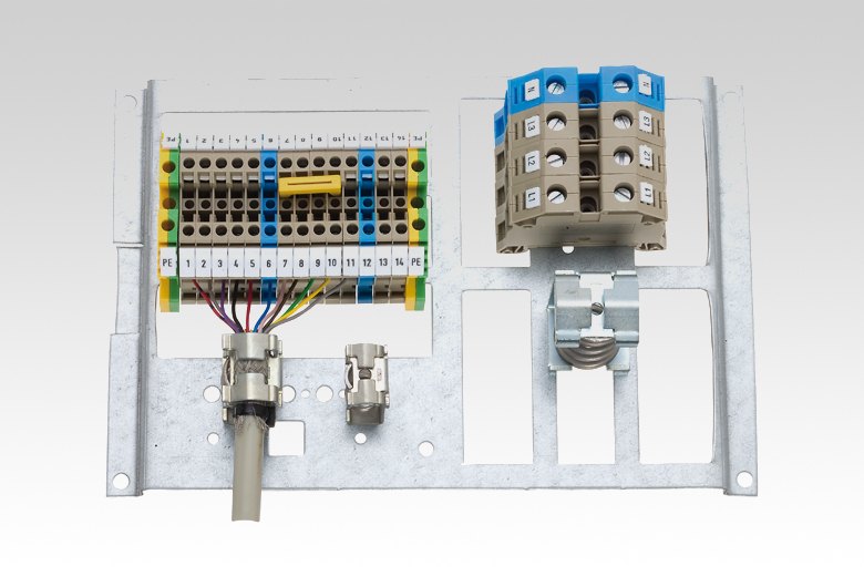
    Shields landed on Conta-Clip shield clips, full circumference, no pigtail.
    Shields landed on Conta-Clip shield clips, full circumference, no pigtail.Photo: Conta-Clip
    PowerSignal90°Cross at a right angle.Coupling is lowest there.
    Where power and signal must meet, they cross.Dynamic drawing
    DriveInput powerMotor cable200 mm (8 in) or more500 mm (20 in) or moreControl, Ethernet, serialExample: the ABB ACS880-01 manual.Use the manual for your drive.
    The inches come from the drive maker's manual.Dynamic drawing

    Dynamic parts

    • Wiska EMC glands terminate the shield at the enclosure wall.
    • Conta-Clip SABK shield clips land the shield inside the cabinet. They snap onto mounting feet for a TS 35 DIN rail, a 10 x 3 mm busbar, or the back panel, with no tools.
    • Celduc solid-state relays switch with no contact bounce, so there are no bounce spikes on the control bus.
    • Brainboxes Ethernet to serial units shorten the serial run, so less of it shares the panel with the noise.

    Other brands we point to

    • Braided sleeving, ferrites and shielded duct: Panduit, HellermannTyton.

    Choosing shield clips, EMC glands or Ethernet to serial hardware for a noisy panel? We help you specify them.

    5

    Bundling

    Inside the panel, duct beats a bundle. A bundle is the right answer for the door harness, for runs to devices away from the duct, and for the field side.

    The practice

    • Use duct where conductors run along the back panel. Duct keeps conductors cooler, easier to trace and easier to add to.
    • Use a bundle where duct cannot go: the door harness, a run up to a device off the duct line, a cable leaving for the field.
    • Tie snug, not tight. A tie that dents the insulation is too tight.
    • Keep ties off bends. Tie on the straight runs on either side.
    • Space the ties evenly, and put one at every breakout where a conductor leaves the bundle.
    • Cut tie tails flush. A sharp tail cuts the next technician's hand.
    • Use screw-mounted tie mounts in a hot enclosure. Adhesive mounts carry a lower temperature rating, so check the mount's rating against the cabinet's inside temperature.
    • Wrap the door harness in spiral wrap, so it flexes as one cable across the hinge.
    • Remember that a bundle runs hotter than the same conductors in duct. Bundled current-carrying conductors lose ampacity when more than three share a raceway or cable (NEC 310.15(C)(1)).
    Ties on the straight runs, snug, on screw mounts.
    Ties on the straight runs, snug, on screw mounts.Adobe Stock 407361908

    Dynamic parts

    • None. Conta-Clip wiring duct (section 3) is the alternative to a bundle inside the panel.

    Standard

    • IPC/WHMA-A-620F (2025), Section 14, Securing: tie tightness, damage, spacing, breakouts, routing and bend radius.
    • NEC 2023 310.15(C)(1) for the ampacity adjustment.

    Other brands we point to

    • Cable ties, tie mounts, spiral wrap and sleeving: Panduit, HellermannTyton.

    Choosing the wiring duct that keeps bundles to a minimum? We help you specify it.

    6

    Termination

    Most hot spots at a thermal survey start at a terminal. The wire was landed bare, landed loose, or landed too tight.

    The practice: ferrules

    • A stranded conductor landed bare in a screw terminal frays. It loses strands under the clamp and can bridge to the next terminal. A crimped ferrule turns the strands into one solid pin that seats the same way every time.
    • Use a ferrule on every stranded conductor in a screw or push-in terminal, unless the terminal maker says the clamp takes bare strands. Many push-in terminals take a bare solid conductor directly, and a stranded conductor only with a ferrule.
    • Match the ferrule to the conductor size, and the crimp tool to the ferrule. DIN 46228 sets the sizes (Part 1 bare, Part 4 insulated). UL 486F is the US standard for bare and covered ferrules.
    • UL 508A adds its own ferrule rules (UL 508A, 3rd edition, 29.3.6). Ferrules go on stranded copper only. Each ferrule is rated for the number and size of wires in it, and is crimped with the proper tool before it goes in the terminal.
    • Two ferrule color codes exist, the German DIN code and the French code. Put the one the shop uses on the drawing, so nobody reads a size off the wrong color.
    • Fine-stranded conductors need a terminal identified for that conductor class (NEC 110.14(A)). A ferrule is the usual way to land fine-stranded flexible cable on a standard terminal.
    • Use a ratcheting crimper with the maker's die. Pliers do not make a gas-tight crimp.
    • Take the strip length from the terminal datasheet, not from habit.

    The practice: torque

    • An under-torqued terminal heats, oxidizes and heats more. An over-torqued terminal strips, cracks the housing or cold-flows the conductor.
    • Use the torque on the device datasheet, with a calibrated tool. Where the maker gives a torque, the NEC requires a tool that achieves it (NEC 110.14(D)). The terminal standard behind the values is UL 486A-486B.
    • Values differ by frame, even within one product family. The Schaltbau C320 main terminals are M8 at 10 to 12 Nm. The C303 main terminals are M6 at 5 to 6 Nm. The C310 takes M8 at 4.8 to 6 Nm on the 150 A frame and M10 at 8 to 10 Nm on the 300 and 500 A frames.
    • Put a paint stripe on each torqued fastener, so the inspector and the next technician can see it was done.
    • Do not retorque on a schedule unless the maker calls for it. Repeated tightening work-hardens the conductor.
    • Push-in and spring-clamp terminals have no torque value. The spring sets the clamp force, not the technician.

    The practice: tug test

    • Pull every conductor after you land it. A firm tug proves the clamp took the wire.
    • This matters most on push-in terminals. A conductor that stopped short of the spring can feel landed and still pull out.

    The practice: cross-connections

    • Feed a row of terminals with a cross-connection (a bridge or comb), not a chain of jumper wires. A daisy chain puts two conductors under one clamp and adds a joint at every step.

    The practice: grounding and bonding

    • Bond the back panel, the door and every exposed metal part to the protective bonding circuit (NFPA 79-2024, Section 8.2).
    • Ground the metal mounting panel with a wire-type equipment grounding conductor. Equipment in contact with that panel then counts as grounded (NFPA 79-2024, 8.2.1.2.4, new in 2024).
    • Bond to bare metal. Paint under a bonding point is an insulator.
    • Put two conductors under one clamp only where the terminal maker rates it for two. UL 508A allows more than one conductor at a termination only when every strand is held and the spacings are kept (UL 508A, 3rd edition, 29.3.7).
    1 StripLength from the datasheet2 Ferrule onSized to the conductor3 CrimpRatcheting tool, maker's die4 LandThen a firm tug
    Ferrule, crimp, land, tug.Dynamic drawing
    Conta-Clip ferrules, sized and color coded.
    Conta-Clip ferrules, sized and color coded.Photo: Conta-Clip
    A ratcheting crimper with the maker's die.
    A ratcheting crimper with the maker's die.Adobe Stock 1239162636
    Landing the conductor. Torque to the datasheet, then a paint stripe.
    Landing the conductor. Torque to the datasheet, then a paint stripe.Adobe Stock 1070874576

    Dynamic parts

    • Conta-Clip terminal blocks: PRK push-in, RK and SRK screw.
    • Conta-Clip protective conductor terminals, green-yellow: PSL push-in, SSL and SL screw. Each makes contact with the DIN rail through its PE foot.
    • Conta-Clip PPVK potential distribution terminals: push-in, 6 mm2 feed-in with 1.5 mm2 distribution, pluggable cross-connection. PPVK completed its UL approval in October 2026.
    • Conta-Clip ferrules and crimp tools.
    • Conta-Clip cross-connections, end plates and end brackets.
    • Ask us for the terminal's strip length and ferrule table. It is on the Conta-Clip datasheet, and the drawing should carry it.

    Other brands we point to

    • Grounding and bonding hardware (ground bars, braids, lugs): Panduit.
    • A calibrated torque driver.

    Choosing terminal blocks, ferrules and crimp tools for your terminal list? We help you specify them.

    7

    Marking

    Once the panel leaves the shop, the wire number is the only link between the drawing and the panel. If the number is unreadable, the drawing is useless to the technician at the enclosure.

    The practice

    • Number wires by sheet and line. Sheet 12, line 4 becomes 1204, or whatever scheme the shop standardizes. The number then leads straight to the drawing. Put the scheme on the drawing's first sheet.
    • Label both ends of every wire, and every terminal strip.
    • Labels face up and read left to right or top to bottom.
    • Label the device and the rail, not the duct lid. Lids get swapped.
    • Conductor colors identify function. NFPA 79 sets the US colors (NFPA 79-2024, Section 13.2). The 2024 edition revised 13.2.4.1 to clarify orange, the color for conductors that stay energized with the disconnect off.
    • IEC 60204-1 carries the international colors (IEC 60204-1:2016, 13.2.4). IEC 60445 (2021) is the base standard for conductor identification.
    • A machine sold into both markets carries two color tables. Put both on the drawing.
    • Heat-shrink markers survive solvents and handling. Clip-on and wrap-around markers go on faster after the wire is landed. Pick one and stock it.
    Terminal strips labeled on the device and the rail, not the duct lid.
    Terminal strips labeled on the device and the rail, not the duct lid.Photo: Conta-Clip

    Dynamic parts

    • Conta-Clip TTPCardMAX thermal-transfer printer. One printer and one software print terminal markers, wire markers, device labels and rating plates.
    • Conta-Clip marker cards. They fit Conta-Clip, Phoenix, Wago, Weidmueller, ABB and Siemens terminal blocks, so one printer covers a mixed-vendor panel.

    Other brands we point to

    • Heat-shrink wire markers, wrap-around labels and safety signs: Brady, HellermannTyton, Panduit.

    Choosing a marking printer and marker cards for your shop? We help you specify them.

    8

    Power and heat

    Every amp in a panel becomes heat somewhere. The power supply, the solid-state relay and the breaker are where it collects.

    The practice: power supplies

    • Mount the supply in the orientation its datasheet allows. A supply cooled by natural convection needs air to move through it.
    • Premium's DIN-rail supplies mount vertically, input terminals at the bottom. On the DPX-240, any other orientation cuts maximum output power by 15 percent.
    • Keep the clearance above and below the supply that its datasheet calls for. Duct crowded against the vents traps the heat.
    • Clearances differ by model. The Premium DPX-480 and DPX-960 need 20 mm above and 40 mm below. The DPX-240 needs 40 mm above and 20 mm below. None needs space at the sides.
    • Read the temperature rating, not only the nameplate watts. The DPX-480 and DPX-960 deliver full power from -40 to +60 C and derate above that, to +70 C.
    • Size the supply for the cabinet's inside temperature on the hottest day, not the room's.
    • Protect the input as the datasheet says. The DPX sheets call for a 16 A C-curve circuit breaker.

    The practice: solid-state relays

    • A solid-state relay dissipates heat whenever it conducts. Figure roughly 1 to 1.5 W per amp, and budget it in the cabinet's heat load.
    • Mount the relay on a heatsink sized from the thermal curves on its datasheet. A smaller K/W number is a bigger heatsink.
    • Celduc's okpac relays must be mounted on a heatsink. Celduc's WF heatsinks run from 0.3 K/W to about 2.2 K/W. The relay on a DIN-rail adapter alone is about 6 K/W.
    • Use the thermal grease or thermal pad the relay maker specifies between relay and heatsink. A bare metal joint traps air.
    • Leave space around the heatsink so air can reach the fins. Two hot heatsinks side by side heat each other.
    • Torque the power terminals to the datasheet value. On Celduc okpac relays with M5 power screws, that is 2 to 3 N.m, typically 2.4 N.m.
    • Protect the relay from a load short. Celduc's guidance is a fast fuse with an I2t below half the relay's I2t.
    • A miniature circuit breaker works too, with a relay rated 5,000 A2s or more. Celduc's SOB967660 is the high-I2t okpac built for breaker protection.

    The practice: current transformers and meter wiring

    • Never open the secondary of a conventional current transformer while the primary is energized. SATEC's meter manual says the same. Wire a shorting block, and short it before any work on the meter.
    • Install every current transformer facing the same way, by its polarity mark. SATEC's wiring diagrams show K toward the line and L toward the load. A reversed transformer reads negative power on its phase.
    • Give the meter's voltage inputs a disconnect device, as SATEC's wiring diagrams show. Protect the voltage-sense leads as the meter's installation manual requires.
    • Run the current transformer leads as signal: twisted, away from drive output cables, and crossing power at 90 degrees (section 4).
    • SATEC HACS current sensors have a built-in protection circuit, so they need no shorting blocks.
    • SATEC's HACS install notes: a shielded twisted extension cable with the shield to protective ground, 1.5 mm2 or larger, up to 200 m (650 ft). Run the cable in its own conduit, at least 1 m (3 ft) from high-voltage circuits and strong magnetic fields.
    Premium DPX-240: mounts vertically, 40 mm above and 20 mm below.
    Premium DPX-240: mounts vertically, 40 mm above and 20 mm below.Photo: Premium PSU
    Celduc solid-state relays on heatsinks, with room for air at the fins.
    Celduc solid-state relays on heatsinks, with room for air at the fins.Photo: Celduc
    SATEC HACS current sensors: built-in protection, no shorting block.
    SATEC HACS current sensors: built-in protection, no shorting block.Photo: SATEC
    Every current transformer faces the same way: K toward the line.
    Every current transformer faces the same way: K toward the line.Adobe Stock 1796474657

    Dynamic parts

    • Premium PSU DIN-rail power supplies: DPX three-phase (240, 480 and 960 W) and DPS single-phase. All are convection cooled and operate from -40 to +70 C, with derating at the top of the range.
    • Celduc solid-state relays, WF heatsinks, thermal pads and DIN-rail adapters.
    • SATEC meters and HACS current sensors.
    • IMO circuit breakers.

    Standard

    • UL 508A, 3rd edition, Sections 28 and 29 for wire types and sizing inside the panel.
    • Every number above comes from the factory datasheet of record listed under Sources.

    Other brands we point to

    • Fans, filters and enclosure cooling.

    Choosing power supplies, solid-state relays, heatsinks or metering for your panel? We help you specify them.

    9

    DC specifics

    A DC contactor is not an AC contactor with a different label. The full piece, How to read a DC contactor datasheet, goes deeper. This page is what to check at the bench.

    Why DC is harder to break

    • An AC arc goes out at the next current zero, within about 8 ms at 60 Hz. DC has no zero. The arc burns until the contactor stretches, splits and cools it out.
    • The Schaltbau C303, C310 and C320 use permanent magnets to push the arc up into the arc chamber, where it is split and put out.
    • A magnet pushes the arc one way. A "bidirectional" contactor has an arc chamber built to break current flowing either way. The Schaltbau C303, C310 and C320 are bidirectional by construction.

    Reading the datasheet

    • Thermal current (Ith) is what the part carries continuously. It is not a switching rating.
    • Operational current (Ie) is what the part makes and breaks repeatedly, at a stated voltage and utilization category. It sits far below Ith. The C310 carries 500 A, and its DC-1 Ie is 60 A at 750 V.
    • Breaking capacity is stated at a voltage and a circuit inductance. Read the inductance column every time. A long cable run to a battery string has more inductance than the test circuit.
    • Making capacity decides whether the contacts survive closing into a capacitor bank. A precharge contactor and resistor bring the bus up first.
    • Short-time withstand current is the fault the closed contacts carry until the fuse clears. Coordinate it with the fuse the datasheet names.
    • Contact resistance sets the heat. Loss rises with the square of the current.
    • A cycle count with no voltage and current beside it is not a rating.

    Which event is it for

    • In a battery, storage or charger system, the power electronics do the routine switching. The contactor isolates, carries current for years, and breaks the rare fault. Specify it for that fault: voltage, current and inductance.
    • On a test bench, every cycle opens under load. There, electrical life at the bench's voltage and current is the first number.
    • An AC-3 motor rating says nothing about DC. A battery isolator or bus contactor is DC-1 duty (IEC 60947-4-1).

    At the bench

    • Keep the arc chamber clearances the datasheet gives, on all sides and above. The chamber vents.
    • Mount in a position the datasheet allows. The C320 never mounts upside down. The C310's making capacity drops from 2,500 A horizontal to 2,000 A vertical.
    • Torque the main terminals to the datasheet: C320 M8 at 10 to 12 Nm; C303 M6 at 5 to 6 Nm; C310 M8 or M10 by frame.
    • The contactor is IP00. It goes inside an enclosure.
    • Do not add a freewheeling diode across the coil. The coil suppression is built in, and an external diode slows the opening. The C303 manual says not to.
    • Size the control conductor so the coil sees its voltage range at pull-in, after the drop on a long control run.
    • Use a mirror contact for safety-circuit feedback. A mirror contact cannot read closed while the main contact is closed (IEC 60947-4-1 Annex F).
    • Never unplug a connector under DC load unless it is rated to break that load. Put a switching device upstream (section 2).

    UL, stated exactly

    • The C310 and C320 are UL Recognized Components to UL 60947-4-1, file E116641. The C310's UL general-use rating is 50 A at 600 V DC (DC-1). Confirm any higher figure against the file before it goes on a drawing.
    Schaltbau C310: keep the arc chamber clearances the datasheet gives.
    Schaltbau C310: keep the arc chamber clearances the datasheet gives.Photo: Schaltbau

    Dynamic parts

    • Schaltbau C303, C310 and C320 contactors, and Schaltbau connectors.
    • Premium PSU DC/DC converters.
    • SATEC DC metering.

    Standard

    • IEC 60947-4-1:2018 (Edition 4.0): utilization categories, Annex F mirror contacts. UL 60947-4-1, the harmonized US standard.

    Other brands we point to

    • DC-rated fuses, busbar and lugs.

    Choosing a DC contactor? Have the system voltage, the current, the fault it must break and the inductance in hand, and we help you match the datasheet to them.

    10

    Before the panel ships

    Tick a box only when you can point to the part, the marking or the drawing that proves it. Keep this sheet with the job traveler.

    JobPanelDate

    1Layout

    • Power, control, I/O and field terminals sit in their own zones, each with its own rail and duct.
    • Field terminals are near the cable entry, and devices that get replaced can be swapped without unwiring a neighbor.
    • Spare rail and spare duct remain in every zone.

    2Cable entry

    • Every gland and fitting is rated for the enclosure's Type, and its thread matches the hole.
    • Each gland grips the cable inside its clamping range. A tug on the cable does not reach the terminal.
    • Power, control and signal enter at separate points. Any connector that can be unplugged under load is rated to break it, or has a switching device upstream.

    3Duct and routing

    • Duct fill is at or below 50 percent, and every lid closes without force.
    • No cable is bent tighter than its datasheet radius at a corner, a terminal or the door hinge.
    • The door loop is supported at both ends, and service loops are left at drives, supplies and controllers.

    4Separation

    • Power, control and signal share a duct only where every conductor is insulated for the highest voltage present.
    • Signal, Ethernet and serial cables keep the drive manual's distance from motor cables, and cross power at 90 degrees.
    • Each shield is terminated around its full circumference at the wall or the shield clip. There are no pigtails.

    5Bundling

    • Ties are snug, not denting the insulation, and none sits on a bend.
    • Every breakout has a tie, and every tie tail is cut flush.
    • Mounts in a hot enclosure are screw-mounted, and the door harness is wrapped to flex as one cable.

    6Termination

    • Every stranded conductor in a screw or push-in terminal has a ferrule, crimped with the matching tool and die.
    • Every torqued terminal is at its datasheet value, with a paint stripe. Every conductor has passed a tug test.
    • The back panel, door and exposed metal are bonded to bare metal. A terminal holds two conductors only where its maker rates it for two.

    7Marking

    • Both ends of every wire carry a number that leads to the drawing sheet and line.
    • Every terminal strip and device is labeled on the device or the rail, not the duct lid.
    • Conductor colors match the color table on the drawing (US, international, or both).

    8Power and heat

    • Each power supply is mounted in its datasheet orientation, with the clearance above and below that the datasheet calls for.
    • Each solid-state relay sits on its sized heatsink with the specified thermal pad or grease, and has the fuse or breaker its maker calls for.
    • Current transformer secondaries are shorted or wired to the meter, never open, and every transformer faces the same way. The meter's voltage inputs have their disconnect.

    9DC

    • Each DC contactor is rated to break the fault at the system's voltage, current and inductance, in both directions where current flows both ways.
    • Arc chamber clearances, mounting position and main terminal torque match the contactor's datasheet. There is no external diode across the coil.
    • No connector on a DC circuit can be unplugged under load without a switching device upstream.
    Checked byDateSigned off byDate

    Choosing parts for your next panel? We help you specify them.

    Sources

    Standards are summarized and cited by edition, never reproduced. Every product number comes from the factory datasheet named here.

    Standards

    • NFPA 70, National Electrical Code, 2023 edition: 110.14(A) terminals for fine-stranded conductors; 110.14(D) torque tools; 310.15(C)(1) adjustment for more than three current-carrying conductors; 392.22(B) cable tray fill for control and signal cables. The 2026 edition (published August 2025) keeps these sections; no jurisdiction adopts it before 2026-12-31.
    • NFPA 79, Electrical Standard for Industrial Machinery, 2024 edition: Section 8.2 protective bonding, 8.2.1.2.4 equipment on a grounded metal mounting panel (section numbers read from NFPA's 2024 revision reports, docinfofiles.nfpa.org, 2026-11-09); Chapter 12 conductors, cables and flexible cords; Section 13.1 connections and routing; Section 13.2 identification of conductors (13.2.4.1 revised in 2024 for orange).
    • UL 508A, Standard for Industrial Control Panels, 3rd edition (2018), revised 2025-06-26: Section 10 spacings; Section 28 field wiring; Section 29 internal wiring, with 29.3.6 wiring ferrules and 29.3.7 more than one conductor at a termination. Read in UL Digital View 2026-11-10.
    • IEC 60204-1:2016 (Edition 6.0, with AMD1:2021): 13.1.3 conductors of different circuits; 13.2.4 identification by colour; Table 8 minimum bending radii for forced-guided flexible cables; Annex H measures to reduce electromagnetic influences.
    • IEC 60445:2021: identification of conductors by colour.
    • NEMA 250; UL 50 and UL 50E; IEC 60529; IEC 62444; UL 514B; DIN 46228-1 and 46228-4; UL 486A-486B; UL 486F; IEC 61984; UL 1977.
    • IPC/WHMA-A-620F, Requirements and Acceptance for Cable and Wire Harness Assemblies, October 2025: Section 14 Securing (14.1 restraining devices, 14.2 breakouts, 14.3 routing). Table of contents, https://www.electronics.org/TOC/IPC-WHMA-A-620F-TOC.pdf
    • IEC 60947-4-1:2018 (Edition 4.0): clause 5.4 and Table 1 utilization categories; Annex F mirror contacts. UL 60947-4-1.

    Manufacturer data

    • Schaltbau C320 datasheet C2217/2605/0 (May 2026) and installation manual V2.0 (2023-10-26); C303 datasheet C2283/2603/0 (March 2026) and manual (June 2025); C310 datasheet C2215/2407/0 (July 2024); LV500 catalogue A86; HV connector flyer A88 (2022).
    • Conta-Clip PPVK product information D11|25 (Nov 2025); TTPCardMAX brochure EN 08|25; KDS cable entry family sheet (Dynamic, approved 2026-09-29); cable tray training deck and brochure; CCI_SABK_Shielding Mounting Clips.pdf.
    • Wiska: wiska.com, read 2026-11-09. EMC glands and accessories (https://www.wiska.com/en/30/cat/203/emc-cable-glands-and-accessories/), including SPRINT NMSKV EMV-Z, NPT (https://www.wiska.com/en/30/pde/10065488/nmskv-14-emv-z.html); HatGLAND HGSM Pack, metric (https://www.wiska.com/en/30/cat/191/hatgland-hgsm-pack-metric/). Brace conduit as carried on the dynamicrep.com Conta-Clip page (claim CC-09).
    • Conta-Clip product finder, read 2026-11-09: SABK 8, no. 17972.0, and SABK 30/MF/35/Z, no. 27245.0; protective conductor terminals PSL (PRK push-in), SSL (SRK screw), SL (RK screw). CCI_SABK_Shielding Mounting Clips.pdf; CCI catalogs 01 and 02.
    • ABB ACS880-01 hardware manual, 3AUA0000078093 Rev V (effective 2026-02-26), cable separation figure, pp. 90-91.
    • Walther-Werke 2024 pin-and-sleeve catalog.
    • Celduc okpac data sheets SO863970, SO869070, SO869970, SOB544330, SOB942660, SOB965060 (S/MON/SOB965060/B, 2021-01-19), SOB967660: heatsink mounting, thermal grease or pad, WF heatsink values and DIN adapter, terminal torque, fuse and MCB protection, checked consistent across all seven 2026-11-09. Celduc "SSR protection" white paper, p. 4 and pp. 10-13. Card-gated reason CELDUC-R17 for watts per amp.
    • SATEC PM172 installation manual BG0399 Rev. A9 (satec-global.com): CT secondary warning, p. 2; wiring diagrams with CT polarity and voltage-input disconnect, p. 20. SATEC HACS Current Transducers brochure: built-in protection circuit, installation recommendations, p. 7.
    • Premium PSU datasheets, premiumpsu.com/datasheets: DPX-240, DPX-480, DPX-960 (CA-750 series, 2026) and DPS-240 (CA-755-1, 2026-04-13): orientation, clearances, temperature range, input protection.

    Dynamic practice

    • "Build a Better Panel: Control Panel Tips and Tricks" and the "UL 508A Control Panel Compliance Checklist" (Dynamic, September 2026).
    • Contact Us
    • About Us
    • Our Story
    • Partner with Us
    ©2026 DMCS® -  All rights reserved. Privacy
    Dynamic Measurement and Control Solutions, LLC